Hi Dave,
Just to make sure I didn't totally wander off the reservation in replying
to your original question, you asked about the ratio of segment length to
conductor diameter. I HAVE heard segment four times the diameter off and on
over the years. However, I'm so far unable to locate that in W7EL's EZNEC
help text (but haven't read it end-to-end since your email), nor have I
ever read a description of a 4:1 limit with programmatic justification
like we have on some issues. The one element I've found ("Acute Angles" in
EZNEC help) concerns a too short segment sometimes causing the center of
one segment to lie inside the volume of another. Your particular model,
with no acute angles, even with 10 cm segments, is nowhere near that
constraint.
I have used 1 foot segments in a one foot diameter conductor as a tower
approximation, with parallel closely spaced #12 wires (also 1 foot
segments) without any issues in EZNEC Pro/4 NEC 4.x, but that was a good
while ago. These days, weird results with towers get a more literal tower
representation with specific modeling of vertical structure and carefully
picked horizontal rungs. Otherwise I never get even close to 4:1. The
question seems to be one of those "rarely in the crosshairs" types, but
I've never specifically run sensitivity tests on segment to diameter.
Apologies for not answering that right off. But other aspects of your
initial communication were waving red flags.
The normal reason I see your kind of question, whether in public
communication on a reflector, or in private correspondence, is that the
correspondent is engaged in a personal algorithmic or heuristic process of
repeatedly adjusting definition specifics and re-modeling an antenna design
to optimize some aspect of the antenna and is trying to stay within the
bounds of effective practice. He already has found a reason to suspect at
least one value in the model specification might render an inaccurate
result.
For myself, the point at which a modeler is trying to make an antenna
better by monkeying with design, and reaches out for comment, is a logical
and polite point to inquire of his knowledge of ALL the usual suspect
entanglement factors which might affect the correspondent's results, AS
WELL AS the one identified. Your inquiry did fit that profile.
My majority experience is that if the correspondent knows about and has
solved the other issues that DO apply, it is most likely that by some means
(e.g. a good local mentor) he has discovered the LIST of such items and
their resolutions and has dealt with ALL of them, making the inquiry
unlikely in the first place. Otherwise, "Have you also heard about this
other thing?" is in order.
To not do that is like the service station attendant dealing with a
customer's inquiry about wiper blades and and NOT mentioning that the
customer's car clearly has a serious oil leak that could ruin the engine if
allowed to proceed to loss of lubrication.
USING MININEC:
The constant advice bandied about is that if any part of an antenna is less
than 1/4 wavelength above ground, then Mininec ground in EZNEC is
ill-advised. The quarter wavelength appears based on some long forgotten
presumption that inaccuracies of dB fractions aren't worth anything to the
end user of an antenna design. Personally, I am suspicious of Mininec
ground at even a half wave. The results I had with it in my early modeling
days turned out nearly always too optimistic. Better to forget Mininec
except for simple beginner-grade examples, the sort of things that can run
without program error in the free demonstration version with it's segment
count limits.
If, to optimize an antenna design, you are watching small changes in gain
or field strength to determine whether small changes in model definition
are increasing or decreasing performance, and to what degree, inaccuracies
of even a quarter dB can defeat the process and are intolerable. Sometimes,
an increase or decrease of only 0.05 dB is enough to show that a small
design value change is moving in the direction of improvement or not.
Knowing which model description change is "better", even just a little
better, moves things forward. And a small pile of dB snippets from this
mildly better aspect and that mildly better aspect can add up to a
significant performance change.
In W7EL's excellent EZNEC help system, under "Real Ground Types", you will
find the following in oversized italic boldface, presumably to make sure
the reader sees it and gets the very firm point he is trying to make. I
quote:
------------------------------------------
"MININEC-type ground is not recommended unless direct connection must be
made to the ground, for example in modeling a ground mounted vertical. High
Accuracy ground should be used in other cases."
-------------------------------------------
Note that W7EL's specified exception for using Mininec does not include
your project.
W7EL's EZNEC help system constitutes an EXCELLENT, searchable text book on
modeling, decidedly worth the read end to end, and decidedly good enough to
provoke the "RTFM" when it's not read and at least carefully considered if
not followed. It's not infallible, of course, but I have found that I need
pro grade reasons and data to argue with it.
In 2002, I finally paid the money for the pro EZNEC and the NEC4 license.
That was over 1k$ at the time, but emphatically worth it in the long run.
It turns out that one must become an expert in the shortcomings of the
lesser programs to keep from wandering into deep pools of inaccuracy using
them. This often forced multiple extra runs of the non-pro version with
variations in the input model data, just to be sure one was not off the
rails.
For that reason, my always running EZNEC Pro/4 double precision, NEC4.2
engine, lots of small segments, and extended accuracy ground saves me a lot
of time. I'm not telling you to go spend a thousand, but the thousand is
how I know what goes on with the ham grade levels, and how easily they can
muck up a result. And why I'm trying to warn you off some stuff.
SOURCE PLACEMENT:
Source placement in a model does not determine what "part" of an antenna
something is. Each model segment is its own locus of calculation. It must
be evaluated versus every other segment. whether high in the air, or
buried, or thick or thin, it has to be evaluated vs. every other segment.
You do not have to put your physical feed at the point of your model feed.
There is a way from the model to estimate the Z outcome at a necessary
physical feedpoint, when using that feedpoint as source in the model
violates a modeling rule.
In main window "Options" dropdown click on power level. Unclick "Absolute
V, I sources". Use 3D plot type, and Step Size of 1 deg. Click on Show 2D
type every time you run FF Plot. The 2D window will show a vertical slice
with the best azimuth for vertical results in Cursor Elev and Gain. The
purpose of 1 degree steps is to make sure that the best gain is always
found, not hidden in the gap between larger steps.
On 20m use 10 cm segment lengths. My personal method for your model would
be to make the lower 3 segments of the vertical element a wire of the same
diameter as the radial legs. Put the source in the center segment of this 3
segment wire. Finish the vertical with the actual diameters and lengths,
except the lowest with 30 cm less than actual. I mostly use gain results to
ferret out situations where a given segment's answers (including feed Z)
are compromised. I will use that even if the issue is impedance, because
impedance changes NORMALLY from segment to segment, whereas gain in a small
region of segments should NOT vary when changing small segments, making
issue detection possible.
Run the model multiple times while varying the voltage source placement one
segment at a time, segment one to six or seven. The best 2D gain in an
"elev slice" should change very little placing source in segments two,
three and four. You will likely note a value for the gain somewhere in
segments two through seven which is steady to the hundredth of a dB.
Segment one is likely the really odd one. I sometimes see 10 or more times
the change Seg1 to Seg2 versus change Seg2 to Seg3
ESTIMATING FEED FROM 1 OR 2 SEGMENTS AWAY from physical feed:
The process is to take the difference between Seg 2 and Seg 3 and in turn
subtract that from Seg 2. Algebraic treatment of subtraction of negative
numbers applies.
Take the feed point Z, as R +jX, with the source at first, second and third
segments up.
Rres = (2 times Rsub2) minus Rsub3
Xres = (2 times Xsub2) minus Xsub3
Estimated Z when source is center of segment 1 is Rres + jXres
Derivation:
Rres = Rsub2 - Rdiff
Rdiff = Rsub3 - Rsub2
Rres = Rsub2 - (Rsub3 - Rsub2) = Rsub2 - Rsub3 + Rsub2 = (2 x Rsub2) - Rsub3
Same for X.
If you have suspicions about doing this at segment 2 (because the gain at 2
has not settled down yet) and would rather use segment 3, then take the
difference between Seg 3 and Seg 4 and subtract TWICE that from Seg 3.
Derivation:
Rres = Rsub3 - (2 x Rdiff)
Rdiff = Rsub4 - Rsub3
Rres = Rsub3 - 2 x (Rsub4 - Rsub3) = Rsub3 - (2 x Rsub4) + (2 x Rsub3) = (3
x Rsub3) - (2 x Rsub4)
Same for X
I have gotten to the point I just always use segment 2 for the model's Z.
The variations are small enough IF using small segments that it turns out
to be not worth it once one is cutting tubing and wire. The variation in Z
and frequency of X = 0 caused by the ACTUAL ground and ACTUAL environment
swamps the difference between Seg2 and corrected Seg2 in the model.
Persistent improvements in accuracy occur when one is chasing gain and
efficiency. Which is why I no longer even remotely consider R + jX until
I've worked through gain and efficiency. IF the R + jX at that point is
simply difficult or unmanageable, THEN I will go back and work to improving
feed Z. But I will have the best gain and efficiency in hand and know what
I am trading off.
Please note that any dipole-ish antenna's feed impedance and resonant
frequency vary considerably with height above ground for the same length of
wire. That is a physical fact, not an artifact of modeling. This variation
can also occur with miscellaneous conductors within several wavelengths or
proximity to large dielectric masses. Modeling will demonstrate that
variation if the circumstance can be entered into the model data.
COAX SHIELD AND COMMON MODE
The way to model the coax shield is to connect a vertical wire to the
radial connection point as if it were another radial wire. Then extend the
wire and add wires parallel to the ground to the point where you have
grounded the incoming coax, at entrance to the house, or in the shack.
If you grounded it entering the house, in NEC4 I would take a small wire
down to earth from the "shield" wire and then add a wire that amounts to a
ground rod. In NEC2 one has the problem that connection to non mininec
ground is a problem. On 20m add another wire 5 meters long and and leave
the end unconnected. That will simulate a "ground" for purposes of common
mode current.
If you didn't ground it, then leave the end of the wire alone.
Use the view antenna window with the view dropdown menu. Click on
"Objects..." . Make sure "Currents" is checked. Leave "Current Phase"
unchecked. Use an EZNEC "Load" in this added wire to specify the placement
and characteristics of common mode blocking (CMB) devices. You may be
lucky, or you may need one or two CMB's.
You may be surprised by the degree of current on that wire. Understand that
common mode current (CMC) on the feedline is a frequent source of local
noise much louder than the same noise as detected on the antenna elements
proper. CMC is also a source of RFI to the house.
While many can get away not dealing with those, others find it debilitates
their radio efforts. CMC can wreck the intended feed Z. Note the effect on
feed Z as add/move CMB's on the "shield" wire.
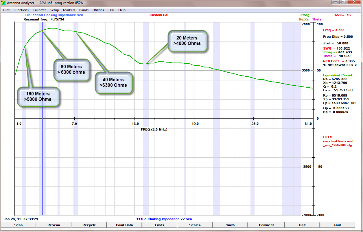
Good CMB may require CMB devices at the feed point AND a physical 1/4 wave
below the feed. The CMB should be effective at the LOWEST frequency you
ever intend to use at your location. Many low band antennas have been
derailed by high band feedlines functioning as unintended and surprisingly
lossy parasitic elements. I have a number of cases among my correspondence
where a 160 L over FCP **could not be properly tuned** due to feedlines to
dipoles, inverted vees on higher bands, sometimes more than 200 feet away.
Those were generally solved by using baluns with specified blocking on 160
[1], and sometimes a CMB at the bottom of the vertical stretch of
feedline.
[1] see
https://cdn3.bigcommerce.com/s-4q7cv/product_images/uploaded_images/59f4efa62cbf4-1116d-choking.jpg?_ga=2.138716851.1488448308.1510054614-1676938941.1510054614
for a Balun Designs example of published blocking. If you have a friend or
club member with a 2 port VNA, they can measure blocking and feedline
isolation on any balun device you already have.
But model with the coax feedline included, which will tell if YOUR
specifics are sensitive. Put the CMB load in the second segment of the coax
feedline wire from the vertical/radial connection. Set the load to series
and series. Then change the load "R" back and forth from zero to 3000 ohms
[2] to 1E9 (open circuit) and see if the feed Z varies significantly. If it
does, you want CMB of some kind to reduce CMC. CMC on the feed coax causes
loss by coupling ground and also by radiating to unuseful places like your
house wiring. Observe any pattern changes. You may need two CMB's to tame
CMC effects.
[2] the blocking specified by your manufacturer at the operating frequency.
If you REALLY don't give a hoot about gain, or RF current on outside of
feedline shield and really only want a sweet SWR, you can go to the old
time procedure and just monkey with the sleeving of the topmost vertical
tubing and the radial lengths until you get a good SWR. Not too far from
the old exercise of pruning a dipole. But I'm guessing that after a string
of getting beat out in pileups or working a weak one, that you'll be back
to wondering about gain, and mis-radiated power. You can lose dB's if the
RF really likes the feedline shield better than the radials.
73, and absolutely good luck!
Guy K2AV
On Sun, Jul 14, 2019 at 12:10 PM David Gould <dave@g3ueg.co.uk> wrote:
> Hi Guy,
>
> Thanks for the detailed information.
>
> I don't know how to say this any different way, that the base of the
> vertical element (38mm tube) is 10m above ground. The top 1.5m of the
> support mast is fibreglass the remaining 8.5m is aluminium pole. The coax
> will just run down the pole to ground level.
>
> In implementation, the centre of the coax goes to the base of the
> vertical. The braid of the coax is connected to two tuned (to 14.175) wire
> (2mm) radials drooping down at 45 degrees (I got this dimension by
> modelling separately an inverted V dipole with the two legs drooping 45
> degrees)
>
> I would implement the design with a common mode current choke at the feed
> point, but I did not know that it needed to be modelled, and I have no idea
> how to do this. Is there a reference I can read how to do this?
>
> If the antenna is 10m in the air with tuned radials I do not see how the
> ground type would have much effect. I am using real/MININEC medium - but
> could easily change it if there is a better option.
>
> My source placement does break the first three of your rules. My thought
> is to move the source into the 2nd segment up in the vertical element. This
> would mean that the bottom segment of the vertical then effectively becomes
> part of the radial system, then the effective length of the radials will be
> increased and hence tune to a lower (and unknown) frequency. I can only
> think that my best bet to get the radials back on frequency would be to
> shorten the radial lengths by the length of the bottom segment - does this
> sound reasonable?
>
> I am not bothered about gain, I am mainly interested in getting the feed
> impedance.
>
> 73,
>
> Dave G3UEG
>
_______________________________________________
Antennaware mailing list
Antennaware@contesting.com
http://lists.contesting.com/mailman/listinfo/antennaware
|