I made a plot this evening that might be of some interest. It started with
an EZNEC model (pretty sure one that originated with W5DXP) of a loaded
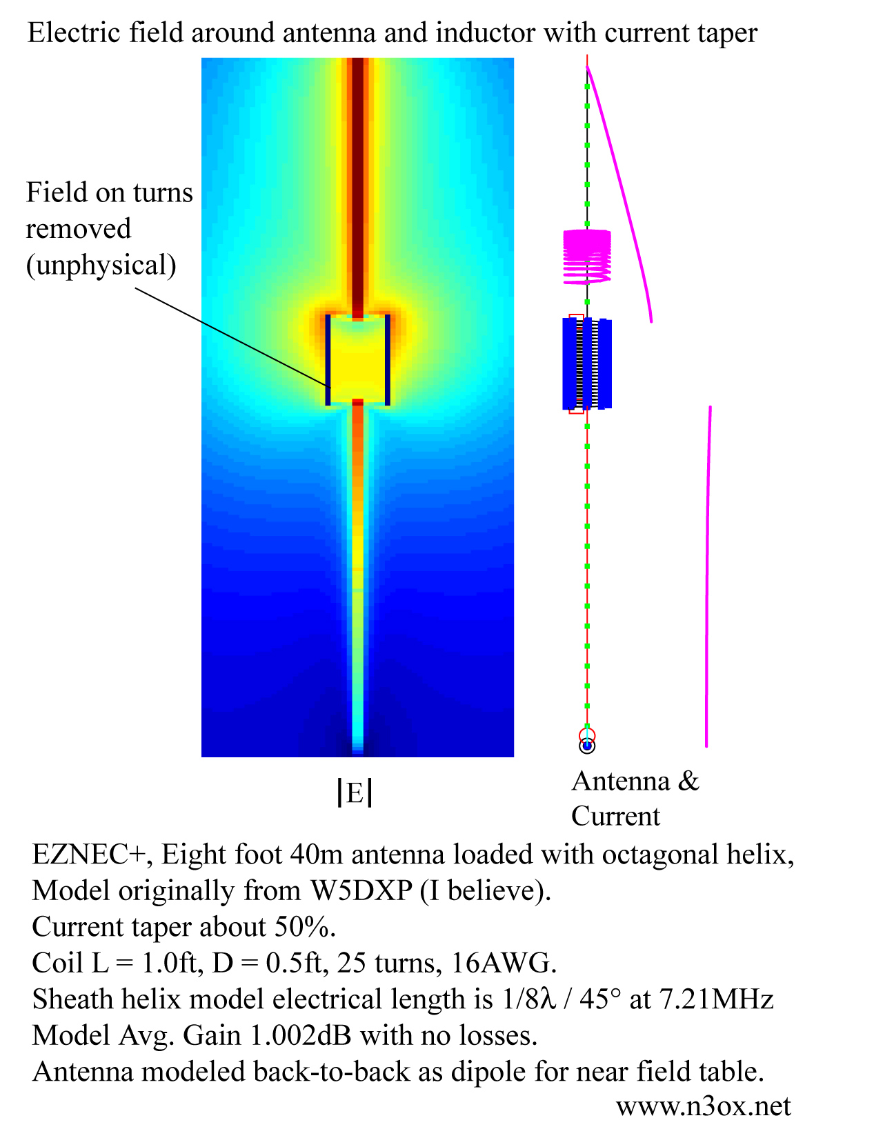
antenna that shows a clear, large current taper. There's only about half
the current at the top of the coil as at the bottom. The antenna is an
eight foot high 40m bugcatcher type antenna with a large (1 foot high, six
inch diameter) coil. I used EZNEC to generate a near field table of
electric field values and plotted the magnitude of the electric field with a
logarithmic** color scale:
http://n3ox.net/files/nf.jpg
I believe that others have objected in the past to NEC-2 modelable coils
being too big for reasonable ham practice. That argument hinges on avoiding
"stray capacitance" as much as possible, and in my opinion, that remains
good advice. However, I don't necessarily think a coil being "too big" or
showing "too much" stray capacitance has that much bearing on what we do to
understand reasons why a coil might show current taper. I think that a
well-behaved NEC-2 model like this one seems to be
http://n3ox.net/files/eznec/real_helix_dipole_40m.EZ
is a reasonable vehicle to aid investigation of some of these things,
provided that we recognize that the quantitative predictions are different
for smaller coils. The limitations regarding closely spaced wires, segment
lengths, and small loops mean we'll need a different mathematical model to
predict the behavior of coils much smaller than this one. I think the
sheath helix model I posted about before is promising, but again, I want to
do more work on the details of that.
Anyway, the strong current reduction seems to go hand in hand with the large
variation in the electric field along the coil. This is similar to what
happens as you approach the end of a dipole, just with a much shorter
wavelength. This is not the last thought I have on the subject but probably
that's about it for now.
"Mobile antenna shootouts" are about as much like real antenna
> engineering as the World Wrestling Federation is like Olympic
> wrestling. Any coil that shows a 60% decrease in current through
> it has a significant amount of unexplained loss.
It doesn't have to have loss.. it just has to have enough electric field to
cause the electrons to bunch up and rarify on the coil structure itself.
An extreme example is the (I think self-resonant) phase reversing coil that
can be found on some VHF/UHF collinear antennas. Such a thing actually has
current flowing in to both ends at once during an instant in the RF cycle,
not in one end and out the other.
The big coil in the above model has about the same current taper with wire
loss turned on and off. That particular taper has nothing to do with loss.
Of course, the radiation goes down when loss is introduced, as would the
current for a constant input power. But the ratio of current out the top to
current in the bottom is about the same in the lossless vs. lossy case.
73
Dan
**I think the final plot is of log(|E|). I'm tired, not taking good notes,
and Octave crashed so I can't check to be 100% sure.
_______________________________________________
UR RST IS ... ... ..9 QSB QSB - hw? BK
|