>
> I was leaning towards the coil for simplicity of construction, yet it needs
> to be at the feedpoint for practical reasons, as it seeds a switching
> circuit with control cable.
>
I use a coil to load my 80m vertical on a fiberglass pole to resonance on
160m. I recently built a computer controlled switch to handle the switching
for me:
http://n3ox.net/projects/stepperswitch/
If you look at the rest of my website you can find older simpler versions,
and also details on my base loading coil.
>
> Does the trap have advantages over the coil, apart from not needing a
> relay?
> Where do I start for practical dimensions to obtain a calculated L value
> for
> the loading coil?
>
The trap needs to be pretty special if you want to use a 1/4 wave 80m
vertical on both bands. You need a circuit that provides a lot of loading
on 160 and not much on 80 but doesn't block all current... I don't know how
easy that would be to pull off without switching plus shunt capacitance is
bad news for good loading coils.
With switching it would be pretty easy, just short out the coil when you
want to use 80m.
The advantage of having a coil higher up on the vertical is clear: the
higher up the loading coil is, the higher the radiation resistance. Now,
the coil has to be much larger if it's halfway or 2/3 of the way up the
vertical, and on a tapered vertical it might have to be MORE reactance with
smaller wire (for weight and windload) so you have an interactive design
problem.
The best way to determine what you want to do, in my opinion, in any of
these situations is to model the antenna in EZNEC or other modeling software
with a realistic coil Q and see how things work out. You can build a giant
copper tubing coil at the base in a way that you can't up high. Trying to
build some dual band loading network will compromise on the lower band, for
sure, but maybe it doesn't matter. You should also try to estimate your
ground losses compared to practical loading schemes.
> Then I stumbled across the linear loading solution in ON4UN's book. I could
> go up and down once with the verttical wire before going up all the way,
> and
> switch the loading part in or out for 160/80.
>
I like how W8JI puts it, from his website:
"Linear Loading is really nothing other than a poor form-factor inductor"
I like coils. I think hams have been fed a load of nonsense from antenna
marketing departments that claim that their design has "no lossy coils."
Coils have loss, it's true, but so does EVERY loading scheme, even if it
just looks like "some wires." The loss of the wire in a linear loaded
antenna is NOT the same as the loss in the same wire stretched out straight!
The loading scheme still has to store and supply a large amount of energy,
and high currents result. Much higher currents than those in a dipole or
something.
People find it conceptually attractive, but I think they often have the
wrong concept in mind when they choose linear loading. Linear loading is
the use of an inductive transmission line stub to load the antenna. It's
difficult to see the stubs sometimes, because each linear loading wire in
between the outer extremes does double duty as one side of two different
transmission lines.
For very SHORT short circuited transmission line stubs, losses aren't so
bad. But once you need a few hundred ohms of reactance it becomes a rather
poor idea. If you need thousands of ohms of reactance it becomes really
terrible.
My wire vertical requires about 640 ohms of reactance to base load it. A
good coil probably has realistic Q in the 300-500 range (from what I gather,
to get 500 you need a pretty special coil, some good info here:
http://www.qsl.net/ve6wz/CC_coil.html )
I can use VK1OD's two wire transmission line calculator to calculate the
input impedance of a shorted stub of practical design...
http://vk1od.net/calc/tl/twllc.htm
let's say 2mm wire spaced 30mm. Approximately 25m of this line shorted at
one end with a 0.000000001 ohm load has an input impedance of 6+j646. This
is indeed a loading inductor of about the right size... but the Q of this
inductive stub is about Q = 108 (646/6)!
I'm convinced you will always do better with a coil.
Some people think the stub radiates, but it can't do that. Unless you put
VERY large spacing, you'll find that the radiation from the currents in the
three wires are just like the radiation from the single vertical, because
the currents in the linear loading setup have phases opposite each other.
You'd have to build a loop, not something that looks anything like a
vertical or "folded" vertical to get any radiation to speak of from the
various wires.
Even with 30cm spacing, they're still transmission line stubs. Wider
spacing is generally better because you need less length of stub to get a
given reactance. Of course, the limiting case is SQUARE... in which case
you just built a large single turn square inductor!
Now, whether or not you need to *worry* about loading system Q really
depends on your ground system. If you've got a total of 1.5 ohms loss
resistance normalized to your feedpoint with whatever loading method you
use, and you're like me and have something like 12 ohm ground resistance for
your radial system on 160m, then there's not much point trying to make the
ultimate Q inductive load.
But in my opinion, once you are able to calculate a coil's physical form
from the reactance you need (lately I've been using
http://hamwaves.com/antennas/inductance.html, I've also used a program
called SOLNOID3 by the late G4FGQ) , they are the simplest and best method
for inductive loading. Linear loading is MORE complicated and MORE lossy.
So the only real advantage is .... what?
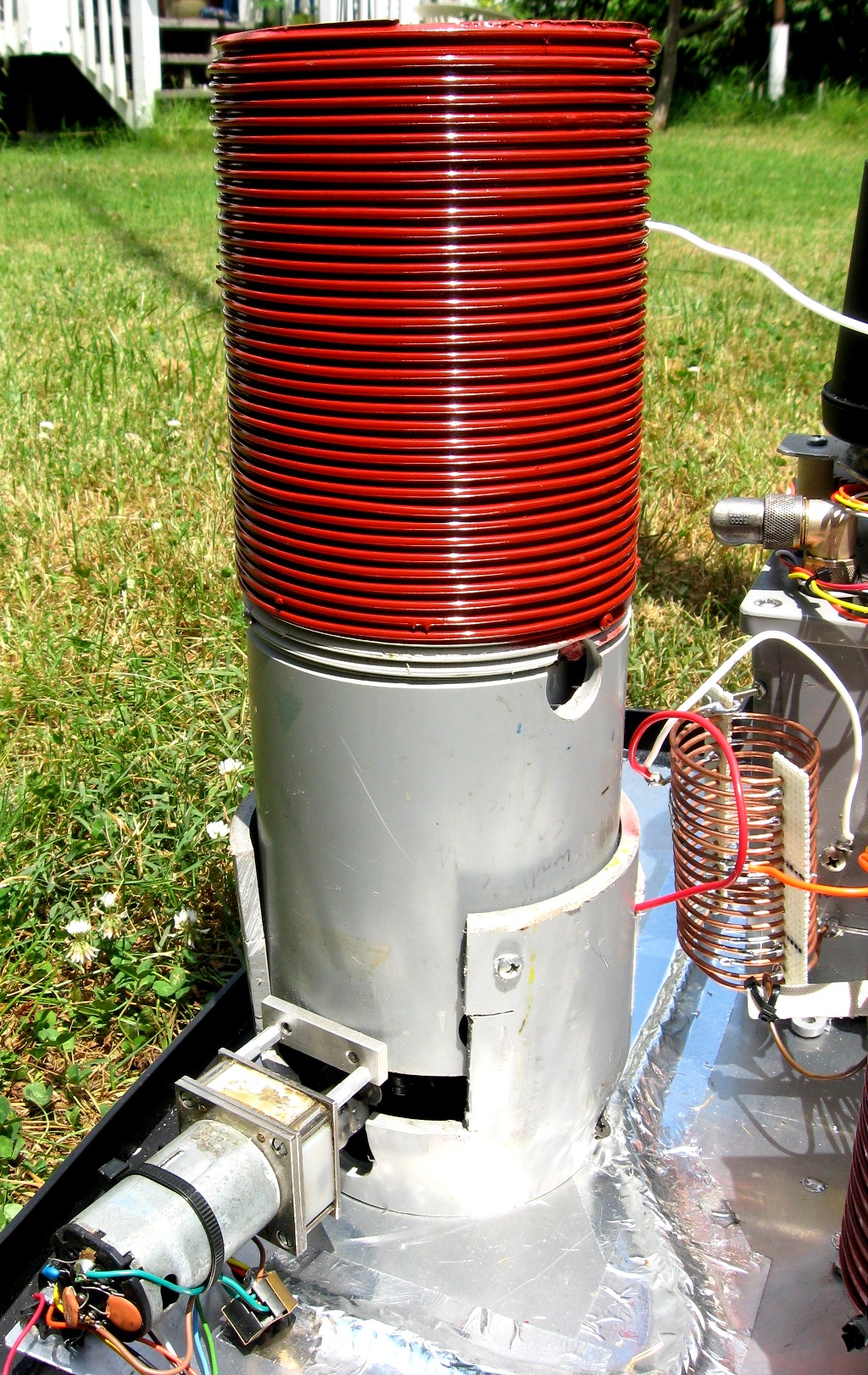
Besides, I think coils are beautiful and very "ham radio looking",
especially my refurbished one for 160m:
http://n3ox.net/projects/stepperswitch/160_match_lg.jpg
Now, regarding top loading vs. base loading, there is good reason to
increase radiation resistance, but in my case since I have one slim
Spiderbeam pole, no trees and my vertical is used on 30, 40, 80 and 160, I
decided to do the simplest thing mechanically and live with base loading. I
estimate I could do about 1dB better with an inverted L but it would require
all kinds of changes that would be adverse for the other bands.
It's important to understand, though, that linear loading probably
***doesn't change the radiation resistance*** vs. base loading if you can
switch it in and out at the feedpoint! This is possibly the worst issue
with linear loading.. it makes it very hard to visualize where the
"inductor" is connected in to the overall system. If you drew a picture
of what you planned to do, I think I could could draw on that picture where
your equivalent loading inductor would go but it's pretty hopeless to do
that in words.
I'd use a coil. If you are only building an 80m/160m vertical, a coil some
distance up the mast would be good if you can handle that mechanically.
N6RK has reported good results using large open frame relays to switch in
and out sections of verticals. I would expect the same to be true for the
loading inductor high in the vertical. If you use a trap, you'll probably
get the best results if you put that right at the top of your vertical and
run a wire off somewhere to make it into a 160m inverted L and 80m vertical.
That would be a really good antenna and would have wider SWR bandwidth
than most other options.
73
Dan
_______________________________________________
Topband mailing list
Topband@contesting.com
http://lists.contesting.com/mailman/listinfo/topband
|